The ZynqMP Processing System (PS) counts with two embedded SPI controllers that can be used to access SPI Flash devices. In this post, we configure the PS SPI to talk to an unsupported flash device, adding support by patching the Linux kernel.
The SPI flash
The Microchip SST26VF032B is populated in this particular hardware board, and until now it was supported by a combination of custom software and a custom firmware IP that does the bit-banging. In this post, we will get rid of all custom code and modify the design to let the PS SPI handle the device, and the kernel to make it look like a system file.
Firmware
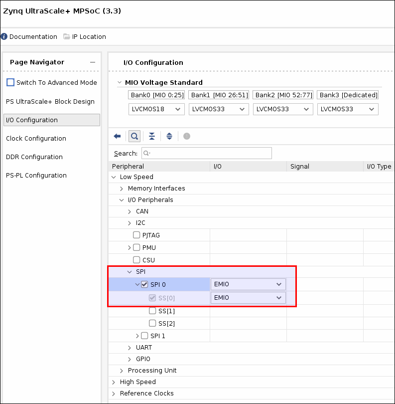
Removing code is usually fun, but when it’s replaced by something more efficient, it’s doubly gratifying. Once the custom firmware code is removed, we enable the PS SPI0 controller in the PS configuration in Vivado, and hook up the I/O pins to the flash device accordingly. Since the pins were controlled by PL, we set the I/Os to EMIO. This will create a set of ports in the block design that will control the pins direction using I/O buffers.
This is the block design wrapper showing the new ports: flash_spi_[io0, io1, sck, ss].
     gpio1_p_tri_io       : inout STD_LOGIC_VECTOR ( 11 downto 0 );
     gpio2_n_tri_io       : inout STD_LOGIC_VECTOR ( 10 downto 0 );
     gpio2_p_tri_io       : inout STD_LOGIC_VECTOR ( 10 downto 0 );
+    flash_spi_io0_io     : inout STD_LOGIC;
+    flash_spi_io1_io     : inout STD_LOGIC;
+    flash_spi_sck_io     : inout STD_LOGIC;
+    flash_spi_ss_io      : inout STD_LOGIC_VECTOR ( 0 to 0 );
     m00_axis_tdata       : out STD_LOGIC_VECTOR ( ADC_IF_WIDTH-1 downto 0 );
     m00_axis_tready      : in STD_LOGIC;
     m00_axis_tvalid      : out STD_LOGIC;
Also shown below are the IOBUF instances that control the I/O direction: (only showing one)
+  flash_spi_io0_iobuf: component IOBUF
+     port map (
+      I => flash_spi_io0_o,
+      IO => flash_spi_io0_io,
+      O => flash_spi_io0_i,
+      T => flash_spi_io0_t
+    );
Then at the top level, at the block design instance, we hook up these bidirectional pins to the top level ports:
+    flash_spi_io0_io          => rom_sdi,
+    flash_spi_io1_io          => rom_sdo,
+    flash_spi_sck_io          => rom_sck,
+    flash_spi_ss_io(0)        => rom_cs_n,
So that’s it as far as firmware is concerned. We removed the old bit-banger firmware module, and enabled the PS SPI controller to connect to the existing flash ports.
Device tree
After we re-build using the exported hardware image (.xsa), we inspect the device tree that Petalinux generates automatically, in the ./images/linux directory.
dtc -I dtb -O dts -o system.dts system.dtb
In the device tree, we see the SPI0 controller is now enabled:
spi@ff040000 {
  compatible = "cdns,spi-r1p6";
  status = "okay";
  interrupt-parent = <0x04>;
  interrupts = <0x00 0x13 0x04>;
  reg = <0x00 0xff040000 0x00 0x1000>;
  clock-names = "ref_clk\0pclk";
  #address-cells = <0x01>;
  #size-cells = <0x00>;
  power-domains = <0x0c 0x23>;
  clocks = <0x03 0x3a 0x03 0x1f>;
  is-decoded-cs = <0x00>;
  num-cs = <0x01>;
  phandle = <0x67>;
};
So we need to tell Linux about the flash device we’re connecting to, as it has no way to know from the firmware design. We add an entry within the SPI controller entry above in our system-user.dtsi:
&spi0 {
  flash@1 {
    compatible = "sst26vf032b", "jedec,spi-nor";
    reg = <0x00>;
    spi-max-frequency = <50000000>;
    #address-cells = <0x01>;
    #size-cells = <0x01>;

    flash@00000000 {
      label = "cal-rom";
      reg = <0x00 0x400000>;
    };
  };
};
We specify that the flash device is handled by the spi-nor generic driver (or should…), the SPI max frequency of the device in Hz, and the name of the sole partition “cal-rom”. So far, so good.
Petalinux boot
When we boot the target, we’re welcome by the following message, indicating the flash device has been accessed but the JEDEC ID is not known to the device driver.
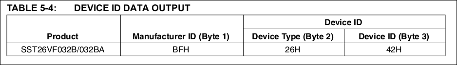
[ 3.749023] spi-nor spi1.0: unrecognized JEDEC id bytes: bf 26 42 bf 26 42
The datasheet for the flash device shows these numbers match:
Device driver
The source code for the driver is in the linux-xlnx git repo under drivers/mtd/spi-nor/spi-nor.c. Inspecting the device driver, we find there’s two devices that very closely match ours:
{ "sst26vf016b", INFO(0xbf2641, 0, 64 * 1024, 32,  SECT_4K | SST_GLOBAL_PROT_UNLK) },
{ "sst26vf064b", INFO(0xbf2643, 0, 64 * 1024, 128, SECT_4K | SPI_NOR_DUAL_READ | SPI_NOR_QUAD_READ) },
We see the INFO macro definition to help figure out what those arguments mean:
#define INFO(\_jedec_id, \_ext_id, \_sector_size, \_n_sectors, \_flags)
So, we’ll have to “insert” our device there with the proper capabilities, patching the kernel.
Patching kernel
Petalinux counts with a feature that allows to patch a given source (U-Boot, Kernel, etc.) and copy the sources into the meta-user area, to keep in the build. First, we have to petalinux-config to change the build tool to devtool. For some reason, setting it to bitbake produces strange results, YMMV.
# petalinux-build -c kernel -x modify
This command will leave the Linux tree under the components directory, ready to be modified. Look under
The device is defined as 64*1024 sector size x 64 sectors = 0x400000 bytes (4 MByte = 32 Mbits). This size parameter is also set in the device tree entry above.
{ "sst26vf032b", INFO(0xbf2642, 0, 64 * 1024, 64, SECT_4K | SST_GLOBAL_PROT_UNLK) },
Once the changes to spi-nor.c are made, we need to git-commit them.
# git add spi-nor.c
# git commit -m "Add mx66u2g45g spi-nor device"
Then we “finish” the kernel edit with:
# petalinux-build -c kernel -x finish
Petalinux then should copy the kernel patch to the meta-user area under recipes-kernel. Be careful if you have other patches there, because devtool will overwrite them. I’d copy them somewhere safe, and then copy them back.
New boot smell
Booting with the new changes looks much better:
root@DAQ16-2020:~# dmesg|grep spi
[    5.490138] spi-nor spi1.0: sst26vf032b (4096 Kbytes)
[    5.495201] 1 fixed-partitions partitions found on MTD device spi1.0
[    5.501546] Creating 1 MTD partitions on "spi1.0":
[    5.674365] zynqmp-qspi ff0f0000.spi: ignoring dependency for device, assuming no driver
[    5.685249] spi-nor spi0.0: mt25qu512a (n25q512a) (131072 Kbytes)
[    5.691363] 4 fixed-partitions partitions found on MTD device spi0.0
[    5.697710] Creating 4 MTD partitions on "spi0.0":
We have the spi1.0 device connected to our flash, and the spi0.0 connected to the existing QSPI device. We can show all mtd devices, partitions and properties:
root@DAQ16-2020:~# cat /proc/mtd
dev:    size   erasesize  name
mtd0: 00400000 00001000 "cal-rom"
mtd1: 02600000 00002000 "boot"
mtd2: 00040000 00002000 "bootenv"
mtd3: 00040000 00002000 "bootscr"
mtd4: 05980000 00002000 "kernel"
We can also read the /dev/mtd0 device and dump its contents:
root@DAQ16-2020:~# cat /dev/mtd0 | od -x
0000000 0000 4400 0000 4400 0000 4100 0000 5100
0000020 0000 3400 0000 0000 0000 0000 0000 0000
0000040 0000 0000 0000 0000 0000 0000 0000 0000
*
Conclusion
We have changed the firmware to make use of the embedded PS SPI controller and after finding the kernel didn’t support our device, we patched it to add support. Less fabric resources and custom software, coupled with more portability and OS support.